Life of an SQL query
This section is a slightly modified excerpt from Section 1, Architecture of a Database System
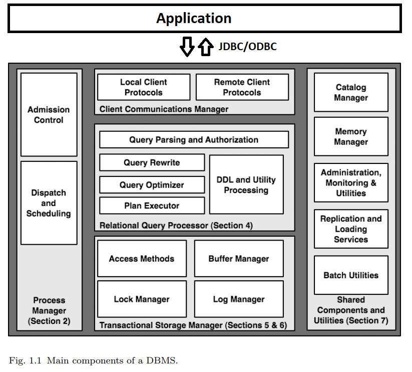
At heart, a typical RDBMS has five main components, as illustrated in Figure 1.1. Consider a simple but typical database interaction at an airport, in which a gate agent clicks on a form to request the passenger list for a flight. This button click results in a single-query transaction that works roughly as follows:
The client software on the personal computer at the airport gate (the “client”) calls an API that in turn communicates over a network to establish a connection with the Client Communications Manager of a DBMS (top of Figure 1.1). In some cases, this connection is established between the client and the database server directly, e.g., via the ODBC or JDBC connectivity protocol. This arrangement is termed a “two-tier” or “client-server” system.
In other cases, the client may communicate with a “middle-tier server” (a web server, transaction processing monitor, or the like), which in turn uses a protocol to proxy the communication between the client and the DBMS. This is usually called a “three-tier” system. In many web based scenarios there is yet another “application server” tier between the web server and the DBMS, resulting in four tiers. Given these various options, a typical DBMS needs to be compatible with many different connectivity protocols used by various client drivers and middleware systems.
At base, however, the responsibility of the DBMS’ client communications manager in all these protocols is roughly the same: to establish and remember the connection state for the caller (be it a client or a middleware server), to respond to SQL commands from the caller, and to return both data and control messages (result codes, errors, etc.) as appropriate. In our simple example, the communications manager would establish the security credentials of the client, set up state to remember the details of the new connection and the current SQL command across calls, and forward the client’s first request deeper into the DBMS to be processed.
Upon receiving the client’s first SQL command, the DBMS must assign a “thread of computation” to the command. It must also make sure that the thread’s data and control outputs are connected via the communications manager to the client. These tasks are the job of the DBMS Process Manager (left side of Figure 1.1). The most important decision that the DBMS needs to make at this stage in the query regards admission control: whether the system should begin processing the query immediately, or defer execution until a time when enough system resources are available to devote to this query.
Once admitted and allocated as a thread of control, the gate agent’s query can begin to execute. It does so by invoking the code in the Relational Query Processor (center, Figure 1.1). This set of modules checks that the user is authorized to run the query, and compiles the user’s SQL query text into an internal query plan.
Once compiled, the resulting query plan is handled via the plan executor. The plan executor consists of a suite of “operators” (relational algorithm implementations) for executing any query. Typical operators implement relational query processing tasks including joins, selection, projection, aggregation, sorting and so on, as well as calls to request data records from lower layers of the system. In our example query, a small subset of these operators — as assembled by the query optimization process — is invoked to satisfy the gate agent’s query.
At the base of the gate agent’s query plan, one or more operators exist to request data from the database. These operators make calls to fetch data from the DBMS’ Transactional Storage Manager (Figure 1.1, bottom), which manages all data access (read) and manipulation (create, update, delete) calls. The storage system includes algorithms and data structures for organizing and accessing data on disk (“access methods”), including basic structures like tables and indexes. It also includes a buffer management module that decides when and what data to transfer between disk and memory buffers.
Returning to our example, in the course of accessing data in the access methods, the gate agent’s query must invoke the transaction management code to ensure the “ACID” properties of transactions. Before accessing data, locks are acquired from a lock manager to ensure correct execution in the face of other concurrent queries. If the gate agent’s query involved updates to the database, it would interact with the log manager to ensure that the transaction was durable if committed, and fully undone if aborted.
At this point in the example query’s life, it has begun to access data records, and is ready to use them to compute results for the client. This is done by “unwinding the stack” of activities we described up to this point. The access methods return control to the query executor’s operators, which orchestrate the computation of result tuples from database data; as result tuples are generated, they are placed in a buffer for the client communications manager, which ships the results back to the caller.
For large result sets, the client typically will make additional calls to fetch more data incrementally from the query, resulting in multiple iterations through the communications manager, query executor, and storage manager. In our simple example, at the end of the query the transaction is completed and the connection closed; this results in the transaction manager cleaning up state for the transaction, the process manager freeing any control structures for the query, and the communications manager cleaning up communication state for the connection.
The right-hand side of Figure 1.1 depicts several shared components and utilities that are vital to the operation of a full-function DBMS. The catalog and memory managers are invoked as utilities during any transaction, including our example query. The catalog is used by the query processor during authentication, parsing, and query optimization. The memory manager is used throughout the DBMS whenever memory needs to be dynamically allocated or deallocated. The remaining modules listed in the rightmost box of Figure 1.1 are utilities that run independently of any query, keeping the database well-tuned and reliable.